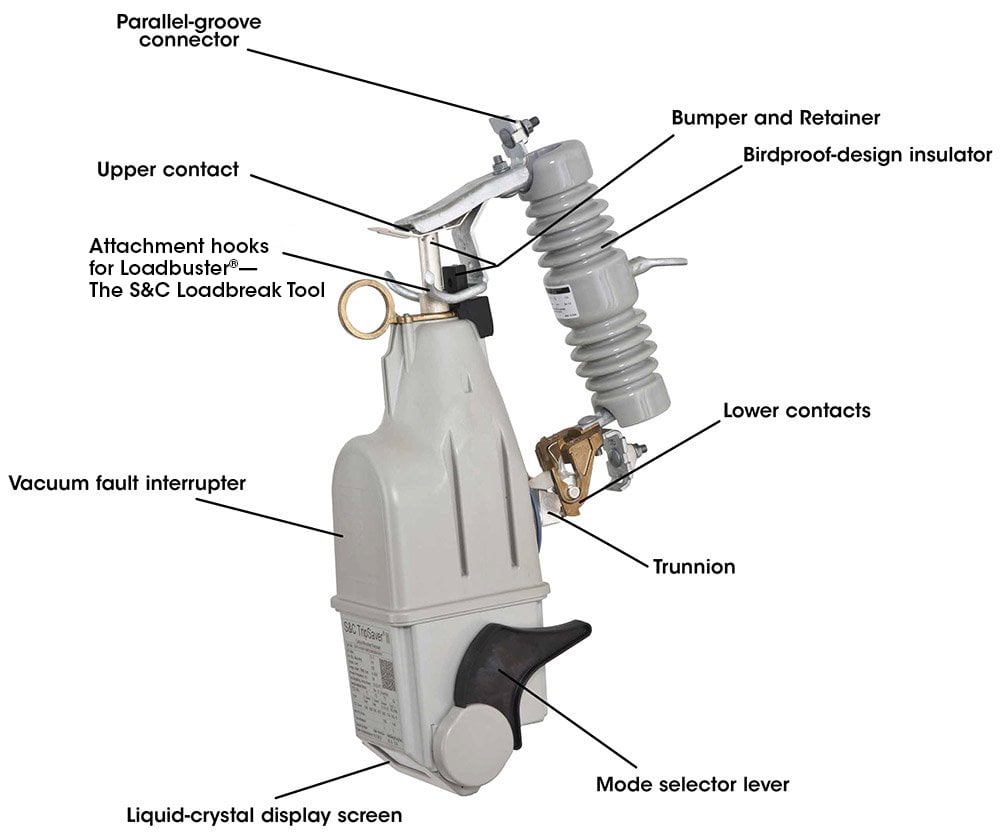
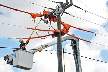
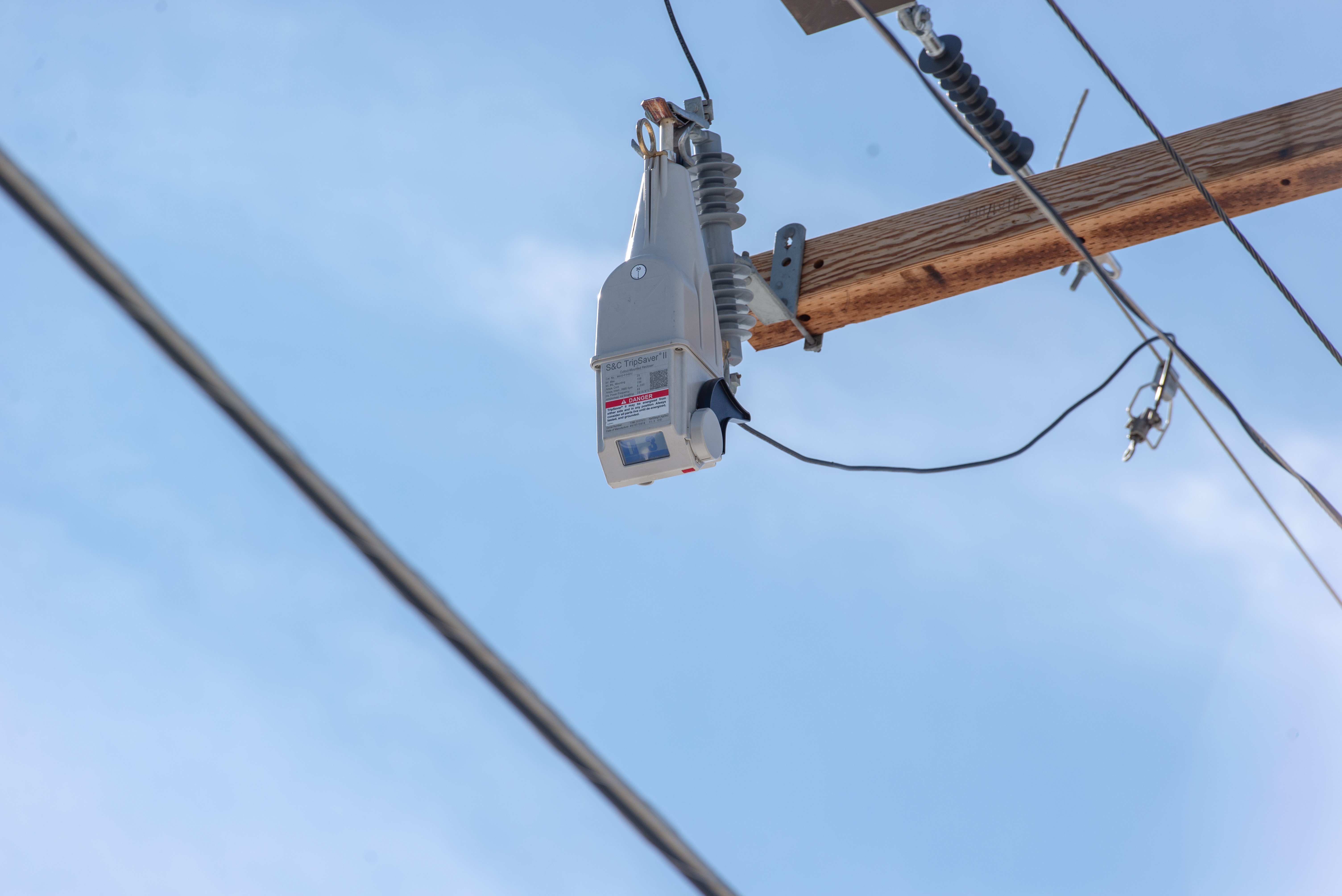
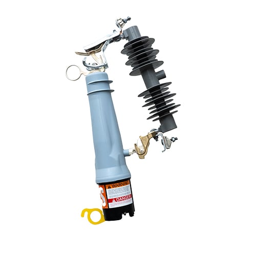
A new lateral protection strategy using S&C's TripSaver II Cutout-Mounted Recloser can dramatically improve the way your utility responds to 80% of faults.
When a fault occurs, this smart grid solution eliminates momentary outages for customers on the main feeder by only blinking the affected laterals.
This approach saves money for the utility and its customers while improving reliability for all.
Overview
Learn how temporary faults are impacting your reliability and bottom line.
Advantages
A modern lateral protection strategy can bring massive benefits to you, your customers, and the environment.
Improves reliability by preventing outages from temporary faults
Learn MoreHelps to avoid unnecessary truck rolls and O&M expenses
Learn MoreImproves customer satisfaction
Learn MoreBenefits the environment
Learn MoreSavings Calculator
Pick a feeder on your system, and calculate how much you could save by using a TripSaver II recloser.
CalculatePounds of CO2 Emissions TripSaver II Reclosers Prevented This Year
*Calculated based on the U.S. Environmental Protection Agency Greenhouse Gas Equivalencies Calculator and utility-reported statistics for S&C’s TripSaver II recloser
Extend the Benefits to Underground Circuits
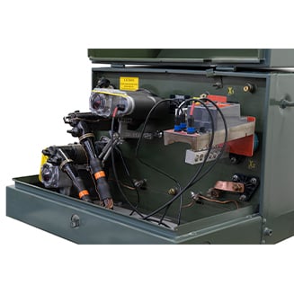
TripSaver II reclosers benefit both overhead and underground lateral circuits. When paired with the EdgeRestore® Underground Distribution Restoration System, these devices eliminate lengthy outages on underground residential lines.
Guidebooks
Thinking about running a TripSaver II recloser pilot or want to check whether you’re optimizing it for the best results? Or perhaps you’re gearing up for widescale deployment and want to be sure you’ve thought through all the steps to come? We’ve assembled best practices from working with utilities like you to share our expertise as you bring TripSaver II reclosers onto your system.
Case Studies
Federated States of Micronesia
Island Nation Enhances Reliability, Resilience with Reclosers
Read Full Case StudyNeed Support?
S&C is here to help you through any stage in your grid-modernization journey, from system studies to installation videos. Explore more below.
Product Details
(On mobile, swipe left for remaining ratings information.)
| 50/60-Hz Ratings① | With Porcelain Insulator | With Polymer Insulator | |||||||
|---|---|---|---|---|---|---|---|---|---|
| kV | Amperes, RMS② | Leakage Distance to Ground Minimum, Inches (mm) | Base Catalog Number | Leakage Distance to Ground Minimum, Inches (mm) | Base Catalog Number | ||||
| System Class | Nom. | Max | BIL | Cont. | Interr., Sym | ||||
| 15 | 15 | 15.5 | 110 | 40 | 4 000 | 8½ (216) | 990511 | 14¾ (375) | 990511-P |
| 6 300 | 8½ (216) | 990611 | 14¾ (375) | 990611-P | |||||
| 100 | 4 000 | 8½ (216) | 990111 | 14¾ (375) | 990111-P | ||||
| 6 300 | 8½ (216) | 990211 | 14¾ (375) | 990211-P | |||||
| 200 | 4 000 | 8½ (216) | 990311 | 14¾ (375) | 990311-P | ||||
| 6 300 | 8½ (216) | 990411 | 14¾ (375) | 990411-P | |||||
| 25 | 25 | 29 | 125 | 40 | 4 000 | 11 (279) | 990522 | — | — |
| 6 300 | 11 (279) | 990622 | — | — | |||||
| 150 | 4 000 | 17 (432) | 990532⬤ | 26½ (673) | 990532-P⬤ | ||||
| 6 300 | 17 (432) | 990632⬤ | 26½ (673) | 990632-P⬤ | |||||
| 125 | 100 | 4 000 | 11 (279) | 990122 | — | — | |||
| 6 300 | 11 (279) | 990222 | — | — | |||||
| 150 | 100 | 4 000 | 17 (432) | 990132⬤ | 26½ (673) | 990132-P⬤ | |||
| 6 300 | 17 (432) | 990232⬤ | 26½ (673) | 990232-P⬤ | |||||
| 125 | 200 | 4 000 | 11 (279) | 990322 | — | — | |||
| 6 300 | 11 (279) | 990422 | — | — | |||||
| 150 | 200 | 4 000 | 17 (432) | 990332⬤ | 26½ (673) | 990332-P⬤ | |||
| 6 300 | 17 (432) | 990432⬤ | 26½ (673) | 990432-P⬤ | |||||
① For 50-Hz applications, specify Microprocessor Control for Application on 50-Hz systems, catalog number suffic "-F".
② Minimum trip current is 5 amperes for 40 A continuous, 5 amperes for 100 A continuous and 10 amperes for 200 A continuous TripSaver II reclosers.
⬤ Applicable for protection of single-phase-to-neutral circuits only in solidly-grounded-neutral (multi-grounded-neutral) 34.5-kV systems where leakage distance to ground meets user's requirement. Uses 25-kV, 150-kV BIL mounting.
Features

TCC Curve Variety
Excellent coordination with other devices.

Local Manual Open
Breaks the load without a loadbreaking tool.

Non-Reclose Mode
Disable the programmed automatic reclosing of the protective device.

Fewer Momentary Interruptions
Cuts momentary interruptions and improves MAIFI performance.

Remote Communications
Communications with back-office system via gateway box option.

Fewer Sustained Interruptions
Cuts sustained service interruptions. Improves SAIFI and SAIDI.

Reclosing Operations
Up to three reclosings before it drops open with a visible open gap.

Restraint Feature
In-rush restraint feature always on. Will not nuisance trip on in-rush.

Operational Status
LCD screens display real-time device status with information scrolling.

Ice Breaking
Capability for device to break ¾" (20mm) of ice.

Gang Operation
All reclosers drop open on three-phase laterals.

Sectionalizing Mode
Can operate as a sectionalizer over a range of fault currents.

Service Center
Service center configurable. Can reconfigure operating sequence.

Microprocessor Control
Line-powered microprocessor control with no batteries needed.

Sequence Coordination
Improves coordination between upstream and downstream reclosers to prevent nuisance momentary outages.

Auto Detect
With version 1.8, single click automatic entry of Transceiver ID eliminates manual entry
Construction
